BX Application Installation Guide
During the pre-production period the BX App is beta quality. It is updated regularly.
- installing the App
- Windows Driver
- Linux Driver
- OS-X Driver
- test the installation
- troubleshooting
Installing the App

The BX App is a Graphical User Interface (GUI) plus a Server. The Server connects the GUI to a USB driver. The USB driver then connects to a BX analyzer on a USB link. Finally, the BX end of the USB link is implemented via an FTDI interface chip with a VID/PID of 0403h/6015h.
The BX App is a Chrome App that you can install from the Chrome Web Store. Click here to install it. This page has more information on installing Chrome apps. And clicking on the following image will also take you to the Chrome Web Store:
If you want to run in Demo mode, the BX App is all you need. If you want to connect to a real BX analyzer, you need the correct USB driver for your operating system. The drivers are implemented via libusb (WinUSB on Windows).
Windows Driver
The easiest way to install a WinUSB device driver is via the well respected Zadig installation system. Make sure you choose the target with a VID/PID of 0403h/6015h and choose the WinUSB driver.
If an FTDI driver is attached to the 0403h/6015h VID/PID it will take control of that port after every reboot. In that case you need to run FTDI's CDM uninstaller to remove the FTDI driver.
Linux Driver
These are the steps for installing the drivers under Linux:
- install the libusb driver
- enable write access to the BX instrument (via a udev rule)
- stop FTDI drivers contending for the BX (via a udev rule)
Install from a Script
Download this zip file for a bash script and a udev rules file. Unpack the zip file and run the script via:
sudo bash bxsetup.sh
Manual Installation
The required driver is libusb-1.0-0, included by most popular installations. If not included, you can add libusb via apt-get or similar:
sudo apt-get install libusb-1.0-0
Make the BX writable to all users by copying this rule to /etc/udev/rules.d:
SUBSYSTEM=="usb", ATTRS{idVendor}=="0403", ATTRS{idProduct}=="6015", ATTRS{manufacturer}=="Bugblat", MODE="0666"
Disable FTDI contention by copying this rule to /etc/udev/rules.d:
ACTION=="add", ATTRS{idVendor}=="0403", ATTRS{idProduct}=="6015", ATTRS{manufacturer}=="Bugblat", RUN+="/bin/sh -c 'echo $kernel > /sys/bus/usb/drivers/ftdi_sio/unbind'"
And finally reload the udev rules:
sudo udevadm control --reload-rules
OS-X Driver
OS-X driver installation instructions are to follow. OS-X driver installation will be very similar in principle to Linux driver installation.
The libusb FAQ has an article on setting up under OS-X. It also references this useful article.
Test the Installation
Plug In the BX
The BX comes with firmware already installed. When idle, this firmware flashes the onboard LEDs in antiphase.
So plug your BX into a USB micro lead (micro is the type of USB lead used in most modern phones, pads, and eReaders) and the LEDs should start doing what LEDs do best.
Confidence Tests
Start the App. The App should start and the serial number of the attached BX analyzer should be displayed in the bottom left corner of the screen, like this:

If the serial number reads Demo check that a BX analyzer is plugged in and the driver has been installed correctly.
USB Device Info
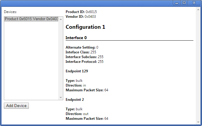
One way to verify the driver is via a Google App which tests specific VID/PID pairs. Click on this image to install USB Device Info from the Chrome Web Store:
Start USB Device Info and here is what you should see if a BX analyzer is plugged in and the driver is correct:

Troubleshooting
- Remember that the BX8 is not galvanically isolated. This means that the inputs must be connected to a target circuit which has the same ground reference as your PC. Usually this is not a problem, but if you suspect that it is causing anomalous readings one solution is to drive the logic analyzer from a laptop computer.
- The BX8 has a combined 5.2Kohm of series resistors in each input circuit so that it imposes a minimum load on the circuit being inspected. Inevitable the BX8 input circuit has a small input capacitance, which must be charged or discharged on each transition of the input signal. This requires a brief input current rush of a few milliamps, and you will get anomalous readings if your circuit cannot drive the current. For instance, a rising edge will be delayed if the test circuit cannot supply enough current to transition the logic analyzer input promptly.
- Ensure that the signal being inspected meets the minimum input specification.

